- Effectively grips thin wall workpiece with minimal distortion at a single chucking pressure.
- Uniformy distributes a 3.6:1 power ratio to the workpiece.
- Six jaws distribute clamping force to twelve equally spaced contact points on the workpiece.
| CHUCK SIZE | 8″ | 10″ | 12″ | 15″ | 18″ | 22″ | 26″ | 30″ |
|---|---|---|---|---|---|---|---|---|
| ASSEMBLY | UBG 8006 | UBG 10006 | UBG 12006 | UBG 15006 | UBG 18006 | UBG 22006 | UBG 26006 | UBG 30006 |
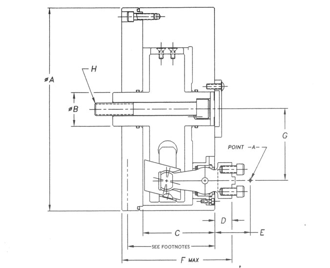
| DIMENSION A | 8.625 | 10.005 | 12.005 | 15.245 | 18.005 | 22.005 | 26.005 | 30.005 |
| DIMENSION B | 1.500 | 1.500 | 2.000 | 2.500 | 3.500 | 3.500 | 3.500 | 3.500 |
| DIMENSION C | 2.444 | 3.875 | 4.232 | 5.375 | 5.610 | 5.610 | 7.312 | 7.312 |
| DIMENSION D | .67 | .87 | 1.00 | 1.22 | 1.50 | 1.50 | 2.063 | 2.063 |
| DIMENSION E | 1.60 | 1.83 | 2.08 | 2.61 | 2.94 | 2.94 | 3.938 | 3.938 |
| DIMENSION F | 4.334 | 5.994 | 6.469 | 8.164 | 8.735 | 8.735 | 11.244 | 11.244 |
| DIMENSION G | 3.1890 | 3.4375 | 4.2500 | 5.5000 | 6.2500 | 8.0000 | 9.1875 | 11.1875 |
| DIMENSION H | 5/8 | 5/8 | 3/4 | 1.00 | 1.00 | 1.00 | 1.00 | 1.00 |
| MAX DRAWBAR FORCE IN LBS. | 5,000 | 10,500 | 12,000 | 16,000 | 18,000 | 18,000 | 18,000 | 20,000 |
| TOTAL DRAWBAR TRAVEL – MIN | .38 | .82 | .88 | .96 | .96 | .96 | 1.00 | 1.00 |
| TOTAL JAW TRAVEL AT POINT A (DIAMETRICAL TRAVEL) | .292 | .440 | .515 | .576 | .617 | .617 | .600 | .600 |
Note #1: Minimum chuck height to be determined upon receipt of machine spindle information.
Shown above is an external grip, centralizing, equalizing chuck. Most chuck sizes are available as standard in external, internal, compensating, centralizing and “centralizing/compensating” styles.